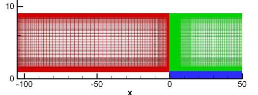
Flow over a backward facing step with height H = 0.5 inches. The computational domain has a height prior to the step of 8H and 9H after the step. The inlet region prior to the step was about 105H and about 50H after the step (see Figure P10.2).
Backward Facing Step Calculations
No slip on bottom walls
No slip on top walls except the first 12 grid points close to the inlet region
Inlet conditions of Uref = 44.2 m/s
No stress condition at the outlet
Fluid properties (obtained from INSTED) and flow conditions
Ma = 0.128
Pref= 13.47psi = 92872.4Pa
Tref =534.16R = 296.756K
ρref= 1.176536kg/m3
μref= 1.82978 x 10⁻⁵ Ns/m2
Re = 35961.8
Figure P10.2. Computational domain
Computational Procedure
Calculations were completed using the MUSCL scheme as well as the compact scheme and the Spalart-Allmaras turbulence model as well as the recently implemented κ-ε turbulence models. The results of the κ-ε turbulence models were compared with the results of κ-ε calculations presented on the WIND website.
The current calculations used three blocks shown in Figure P10.2. The block dimensions are 101 x 131, 138 x 131, and 138 x 55 respectively. The Beam-Warming scheme was used for time integration.
The comparison of the MUSCL and compact scheme are shown in Figures P10.3 and P10.4. The Figures show the comparison of the velocity profile and ūν turbulent stress profile between the compact and MUSCL schemes. The results show that the high-order compact scheme performs better than the low-order MUSCL scheme for the same grid resolution and using the same turbulence models.
Figure P10. 5 and P10.6 represents the comparison of the velocity profile and ūν turbulent stress profile using the κ-ε turbulence model and the compact scheme in AEROFLO compared with the calculations by WIND with the same turbulence model. The results show better performance of the high-order calculations in AEROFLO compared with the experiments. The coefficient of friction, Cf, and the coefficient of pressure, Cp, are also compared in Figure P10.7.
Figure P10.3. Comparisons of u profile between the compact and MUSCL scheme, both having used the Spalart-Allmaras turbulence model
Figure P10.4. Comparisons of uv turbulence stress profile between the compact and MUSCL schemes, both having used the Spalart-Allmaras turbulence model
Figure P10.5. U profiles at selected points along the flow compared with experiments and the WIND calculations
Figure P10.6. uv profiles at selected locations along the flow compared with experiments and the WIND calculations
In the input below, the turbulence type is set at 6 for the Abid model, RESET is set on for turbulence variables to be initialized at the start of the simulation, and PRNS equations are set off.
CF. Steffen, C. J., “A Critical Comparison of Several Low Reynolds Number κ-ε Turbulence Models for Flow Over a Backward-Facing Step”, NASA Technical Memorandum 106173, AIAA-93-1927, June 1993.